Assembly
Connecting the components
SW1Step 1 — Power off
Make sure the power switch is in the OFF position before connecting anything. If your board doesn't have a labelled switch, OFF is the position away from the servo connector (on the other side of the board).
BT1Step 2 — Connect the battery
Plug the battery into the battery connector.
The black (negative) wire must connect to the square pad. Reversing polarity can permanently damage the board.
If you are using an officially-prepared kit, this should not be a problem. We still recommend double-checking for safety.
M1Step 3 — Connect the motors
Connect both motors to the motor output headers.
Motor polarity is not critical - if the robot drives backwards later, swap the wires or invert the direction in the settings page.
If you are struggling to connect the motors, try removing it, then jiggling it around whilst inserting it.
These connections are strong and tight when new, so you may need to use a bit more force. Avoid breaking it, though.
S1Step 4 — Connect the servo (optional)
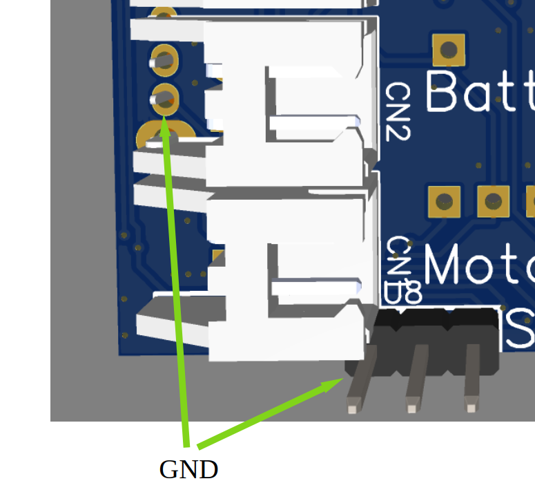
Plug the servo into one of the servo headers. Servo1 is recommended. Using 2 servos will probably not work due to current draw.
The brown or black wire must connect to the square pad. A reversed servo connector can burn out the servo. On the v3 board they are marked gnd(brown/black), hv(red), servo1(yellow/white).
If you are struggling to connect a servo, try removing it, then jiggling it around whilst inserting it.
These connections are strong and tight when new, so you may need to use a bit more force. Avoid breaking it, though.
Charging
The battery charges over the Micro USB connector on the board.
- Turn the robot OFF.
- Plug in a Micro USB cable.
- Wait for the charge indicator LED to show a full charge before unplugging.
Always charge with the robot powered off. The motors draw enough current to slow or prevent charging.
Everything connected and charged? Time for your First Drive.